AXIAL
INDUSTRIAL FANS
AIR MOVEMENT AND INDUSTRIAL VENTILATION
Moro Ventilatori designs and builds axial fans with characteristics and configurations suitable for a wide range of sectors. Executions are available with materials suitable for industrial, food and chemical environments, even in an explosion-proof version, according to the requirements of the ATEX directive (2014/34/EU). Finally, all products comply with the ErP Directive (2019/125/EC) on energy efficiency and performance.
Specifications
The UNI EN ISO 13349:2011 standard defines as axial a fan in which a fluid mass enters and exits the spindle along cylindrical and coaxial surfaces with the axis of rotation of the spindle itself.Construction features
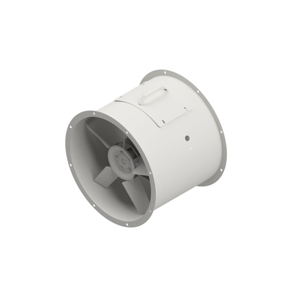
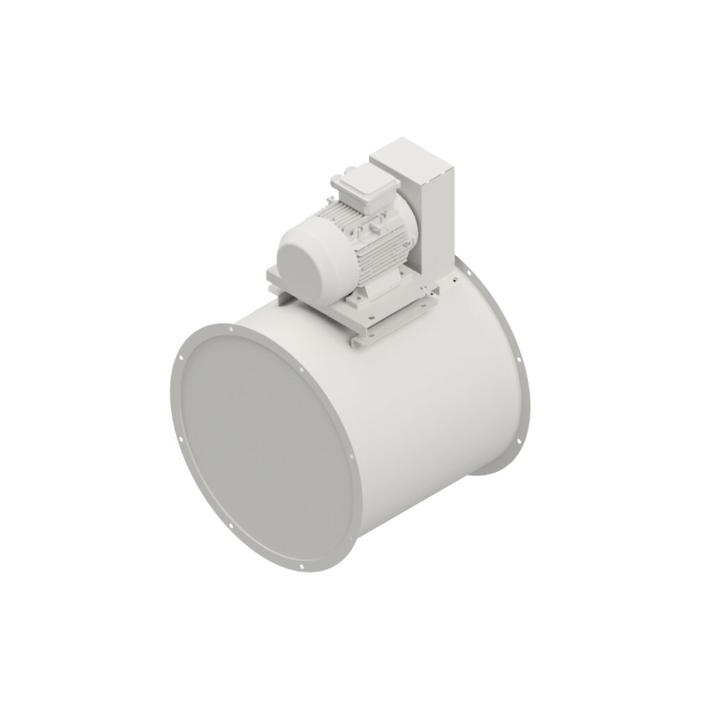
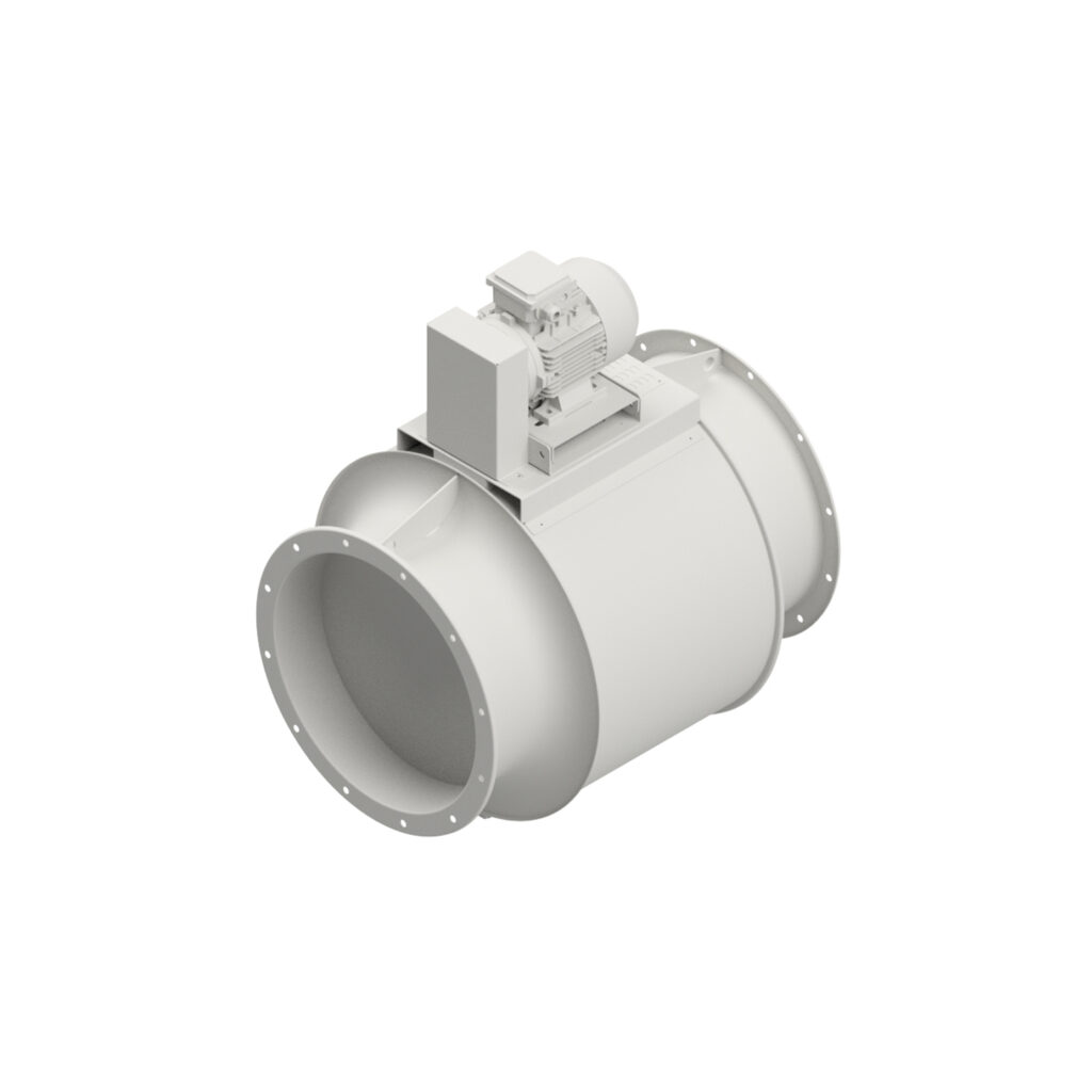
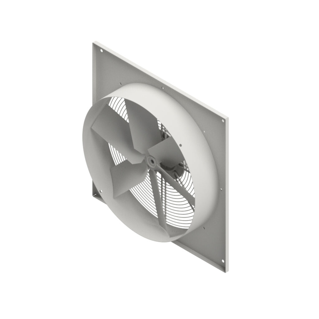
Moro axial fans are designed and manufactured for transport. The different series proposed differ in dimensional and constructional characteristics, in order to guarantee usage under different conditions of use. Executions with direct motor-rotator coupling and belt and pulley versions are available.The purpose of the conveyor is to channel and direct the air flow carried by the fan.
To accommodate different conditions of use, the standard version made of painted carbon steel can be replaced by special versions made of stainless steel or aluminium.
In case of special requests, Moro S.r.l. is available to the customer to evaluate constructive executions made according to specification, with dimensional variations or use of different materials.
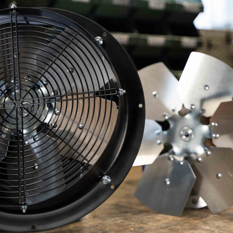
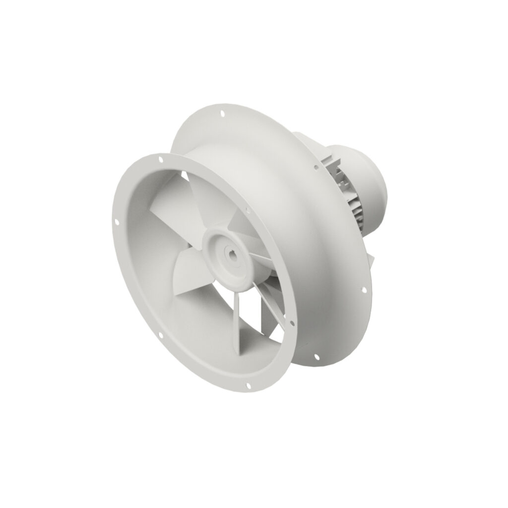
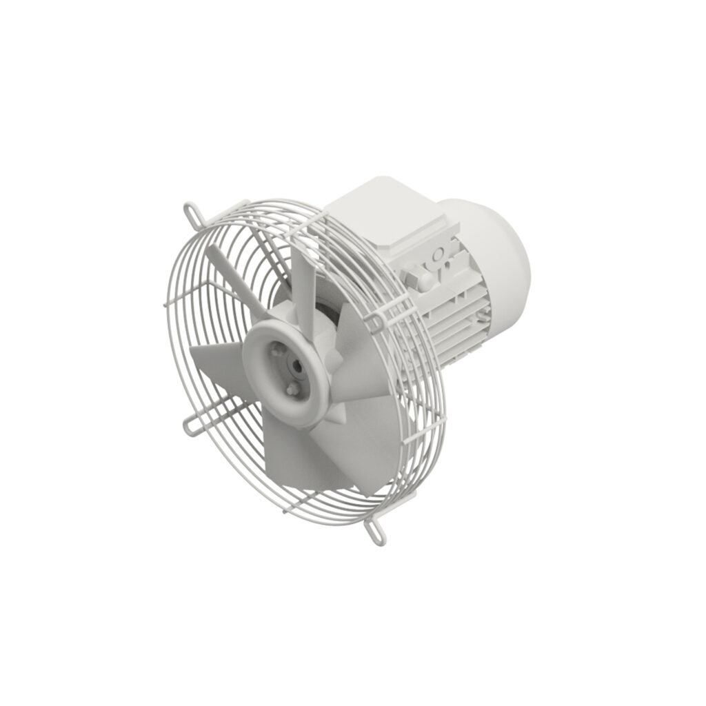
The impeller consists of a hub made of die-cast aluminium and a number of blades that vary depending on the model and are made of different materials depending on the conditions of use. More in detail:
PPG (polypropylene) for operating temperatures from -10°C to +90°C
PAG (glass fibre reinforced polyamide) for operating temperatures from -40°C to +120°C
Aluminium for operating temperatures from -60°C to +250°C
PAG-AS (antistatic polyamide reinforced with glass fibre) for operating temperatures from -40°C to +110°C and non-sparking/explosion-proof executions
Fe360 for operating temperatures from -40°C to +400°C/2h
According to the shape of the impeller, there are two directions of movement of the air inside the conveyor:
TYPE A: Flow from motor (monoblock) to impeller. The motion transmission element is located between the air inlet section and the impeller
TYPE B: Flow from impeller to motor (monoblock). The motion transmission element is located between the impeller and the air outlet section
The impellers, unless otherwise agreed, are statically and dynamically balanced according to the ISO1940/1 standard with reference to degree of balance 6.3.
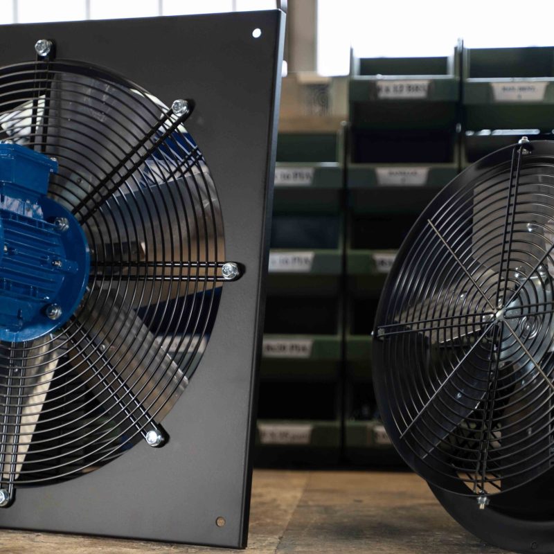
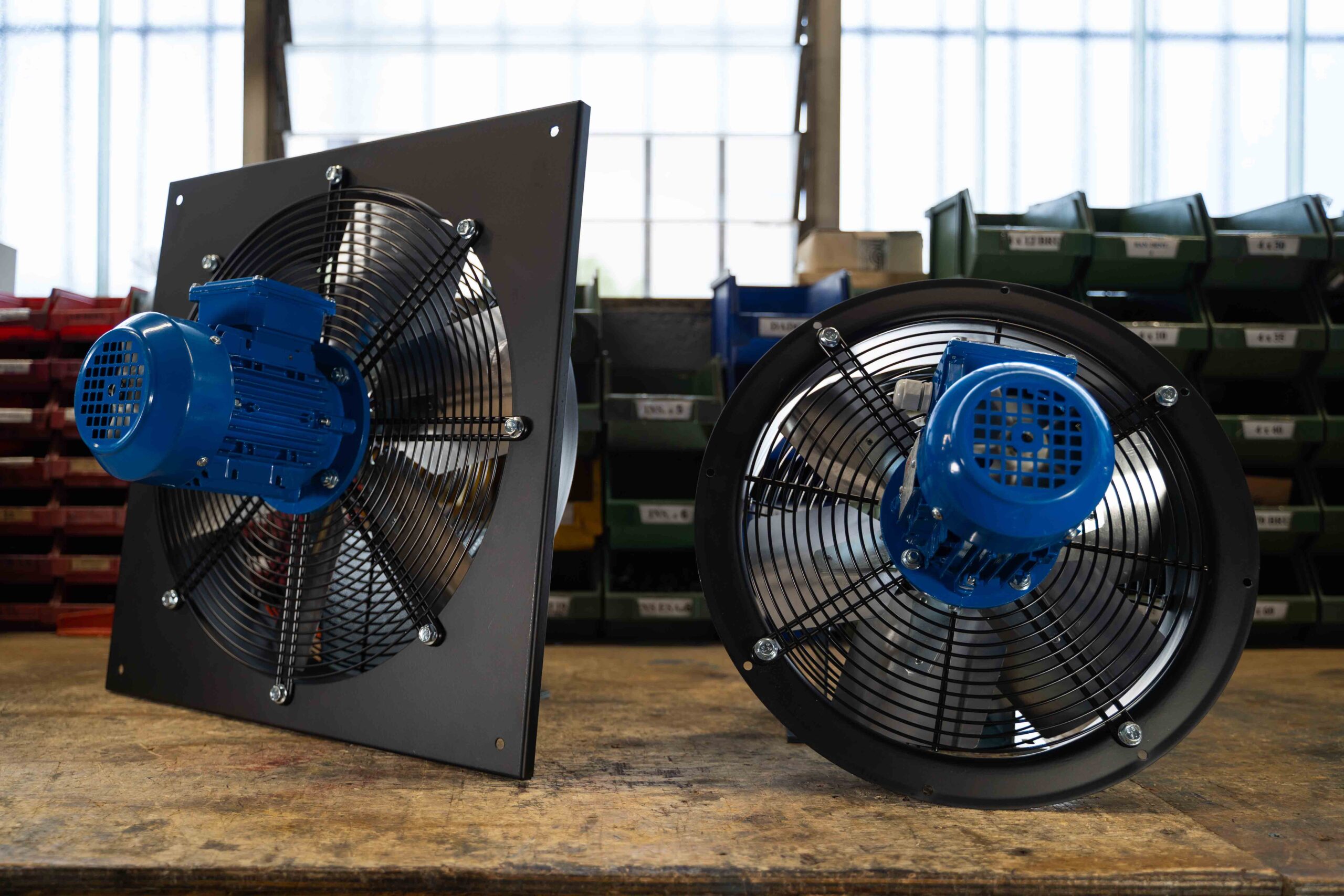
The electric motor, according to the temperature and chemical composition of the fluid, is positioned inside the conveyor and is directly coupled to the impeller or is located outside and transmits the motion to the latter by means of a monoblock and a set of pulleys and belts (TS and EG series).
According to the design specifications, versions with single-phase or three-phase power supply, voltage according to IEC or a special standard, power supply frequency at 50 or 60 Hz are available.
The performance values given in this catalogue refer to a pressure of 1 bar, an altitude of 0 m above sea level and a temperature of 15°C and were obtained by experimental tests carried out according to UNI EN ISO 5801 (cat. B). Unless otherwise specified, the values refer to a power supply frequency of 50 Hz.
The sound pressure data provided are for a fan placed in an open space, connected at suction and discharge, and are obtained as an average of measurements taken at a distance of 3 times the impeller diameter.


